Table of Contents
GCA-PI01 Raspberry Pi HAT (Hardware Attached on Top)
![]()
 Content → Hardware → GCA-RasPi
- GCA-PI01 | Pi01CAN | GCA-PI02 | GCA-PI03 | GCA-PI04 | GCA-Pi05 | GCA-Pi06 | GCA-PI07 | GCA-PI08 | GCA107 Relay board | RocDisplay | Fast Clock
| By Peter Giling |
|---|
“Raspberry Pi" is a trademark of the Raspberry Pi Foundation.
The final design
 |  |  |
| A nice and easy to assemble board is available now. No Surface Mount Devices (SMD) are used. | The Pi01 mounted on the Raspberry Pi B | The Pi01 mounted on the Raspberry Pi B+ |
Description
All GCA interface modules like GCA76, GCA77, GCA93, GCA136 and many others are also adaptable to Raspberry PI.
For that purpose the I2C connection of Raspberry Pi is more than sufficient to get up to 128 I-O lines.
This small board will provide a connection between Raspberry Pi and the GCA-PI02 boards.
Connection between these boards are either RJ12 cable or RJ45 Ethernet, just by selection of the right connector.
All other connectors on Raspberry Pi remain accessible.
Addional, there is a 4 pin connector on board, for future expansion with serial connections.
Supported Raspberry Pis
- Model 1, 2 and 3
- Zero
Raspberry Pi 4 is currently not supported.
I2C system
I2C is basicly made for communication between chips, together on one board.
Therefore, according to specifications , the total length of all SDA and SCL wires together should not exceed 1 meter (3' 4'').
That 1 meter limit is ver strict, meaning that a few centimeters (or even less inches) longer can be a problem.
Important is to know that this 1 meter means ALL the RocNet cables in this Local RocNet network TOGETHER, conterolled by a Raspberry pi.
This system will be made with addional line drivers, making a total length of a few meters more possible.
Each board is provided with an extra line driver P82B715 and a low drop voltage regulator to have 3.3 V available.
The regulator skips the need of transporting 3.3 V from the Raspi, which could give more problems than profit.
But it is also important to realise that the supply over the RocNet cable is only 5 Volt.
And the length of the cabler might be fine for the I2C network uitself, but certainly NOT for the supply in that cable.
And with a little bit of cable length, that 5 Volt will very fast drop down, making the system unstable.
Either RJ12 flatcable or RJ45 Ethernet cable is NOT made for current supply.
So the conclusion here is, use only very short cables, with no more than a total lenght (all cables together!) of 2 -3 meters with one Raspberyy PI.
The extra avaiable GCA_PI06 will provide enough power, but always measure that voltage on the far ends of this RocNet network.
As soon as your voltage there (with the system working) drops down to below 4,8 Volt, you are already too far down.
If you need more I/O you will need multiple Rspberry Pi compters with their own supply.
Raspberry Pi computers are linked to the Ethernet network, and in that ethernet network there are onloy signals, no current.
RocNet is not a 'çheap network', replacing CAN or Ethernet, if your ideas go that way, please reconsider.
For more information about cable length with the line driver, please see http://www.nxp.com/documents/application_note/AN10658.pdf
Hardware
Boards/Kits
Files
| The schematics |
| The pc-board and parts positions |
| The partslist |
| N.B. Only complete ordered kits will be supported! |
|---|
Led functions
| Led1 (green led) | |
|---|---|
| OFF | Program in Raspi not running or no power to PI01 |
| slow flash | Normal function |
| Fast flash | Button is pushed longer that 5 seconds, Raspi will will abort program |
| Led2 (red led) |
|---|
| will flash when show button is pressed in Rocnet screen |
Pushbutton
Holding down PB1 for longer than 5 seconds will abort the RocNet program in the Raspberry Pi.
This button must be activated first on the Options Tab.
Jumper 1
Only place jumper 1, J1, in case the 5V power supply for the Raspberry Pi comes over the RJ12 connector. (Pi06)
Make sure there is no external power supply connected to the Raspberry Pi.
Pin assignment for RJ12/RJ45 connector
| RJ12 | RJ45 | |
|---|---|---|
| Pin# | Pin# | Function |
| - | ||
| - | 1 | GND |
| 1 | 2 | +5V |
| 2 | 3 | SCL |
| 3 | 4 | GND |
| 4 | 5 | SDA |
| 5 | 6 | GND |
| 6 | 7 | +5C |
| - | 8 | GND |
RS232 on S1
By using the Rocnetnode installer the /dev/ttyAMA0 device, connector S1 will be automatically freed from use as terminal.
| S1 Pin Layout | |
|---|---|
| 1 | +5V |
| 2 | GND |
| 3 | Tx |
| 4 | Rx |
Raspberry Pi 3
To enable the /dev/ttyAM0 device for serial communication the following steps are needed:
Disable Serial TTY
Standard the /dev/ttyAM0 is used for TTY communication; Terminal connection:
crw--w---- 1 root tty 204, 64 Feb 9 08:18 /dev/ttyAMA0
But this mode is not usable for normal serial communication, and it should be like this:
crw-rw---- 1 root dialout 204, 64 Feb 10 10:47 /dev/ttyAMA0
Disable the serial TTY on the interfaces tab:

Enable UART and disable Bluetooth in the /boot/config.txt:
enable_uart=1
dtoverlay=pi3-disable-bt
dtoverlay=pi3-miniuart-bt
In case the /boot/cmdline.txt contains console=serial0,115200 this text should be removed from this file.
dwc_otg.lpm_enable=0 console=serial0,115200 console=tty1 rootfstype=ext4 elevator=deadline fsck.repair=yes rootwait quiet splash plymouth.ignore-serial-consoles
Both files can only be edited by the super user: sudo vi /boot/config.txt
RFID
An RFID reader can be connected to the serial port with the following hardware:
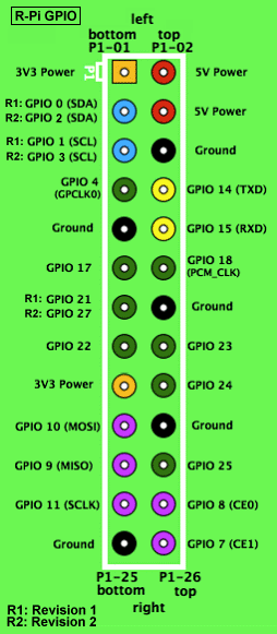
GPIO Pin Layout
The GCA-Pi01 must be connected to pin 1-26.
 If the GCA-Pi01 is misplaced it could damage the Raspberry Pi. (Both models.) If the GCA-Pi01 is misplaced it could damage the Raspberry Pi. (Both models.) |
| Model B | Model B+ |
|---|---|
 |  |
| http://elinux.org/RPi_Low-level_peripherals | http://www.raspberrypi.org/product/model-b-plus/ |
Pin 1
The white square on the Pi01 board marks Pin 1:
| GCA-Pi01 | Raspberry Pi B+ |
|---|---|
 |  |
Make sure that the Pi01 Pin 1 is on the Raspberry Pi GPIO Pin 1 before power on.
(Just double check.)