gca141c-en
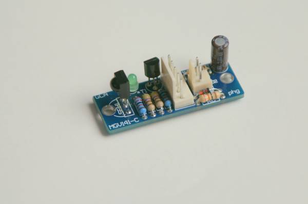
GCA141c The sensor and emittor board.
| By Peter Giling | ||||||
|---|---|---|---|---|---|---|
 | IR led, not on this picture, should be connected to J2 The 5 pin connector is conncted to GCA133 or GCA141 | |||||
To avoid any problems on longer connections between sensor and GCA133 or GCA141 board, the sensor is mounted on a little driver board.
In case of use for GCA141 wheelcounter, the outside of IRled , positioned between the rail, is liable to be short circuited to the rails by train wheels.
Precausions have been made to avoid that ths will cause damage to the IR-led, or any other parts in the system.
Extra power filter is on-board, to make sure the sensor is working according specifications.
The IR led can be connected to J2, or can be mounted straight on board, instead of J2
Hardware of sensor and emittor board GCA141-c
| The schematics |
| The Pcboard and parts positions |
| The bill of materials |
| N.B. Self made pc-boards are not supported! |
|---|
gca141c-en.txt · Last modified: 2018/11/12 08:56 by 127.0.0.1
