Table of Contents
The GCA-Modules
| By Peter Giling |
|---|
The development of technical parts for the railroad has a long history with me.
There usually was not much time while I was travelling around the world, doing my job.
But after that period, I found that many items available in the market of Railroad equipment was either expensive or not good enough, or sometimes even both.
Slowly starting to think about developing it myself, I found that others were already thinking the same way, both in hardware as in software.
One extremely good example is the site you are looking at : Rocrail.
But also Rocrail is nothing (excusez le mot, Rob!) without good functioning hardware.
And because I was a member of Modelspoor Groep Venlo (MGV) the products of my mind slowly began to be called MGVxx, later on even grouped together as the MGV Family.
After trying to 'invent the wheel again' with the succeeding disillusions, I decided to start with LocoNet, actually first on advice of a member of MGV, who was already experiencing with Loconet materials.
Extra tap on my shoulder is that several Rocrail initiators and many users are using GCAxx hardware, sharing my enthousiasm.
The use of interfaces from the GCA units are not restricted to using only with GCA LocoNet.
These interfaces are very well suitable for using anywhere else, with other systems.
All of these units has been made as printed circuit, assembled and tested by members of the Rocrail team and myself.
Where ever that was possible or necessary, I invited other people to help me testing and improving my designs.
Therefore, special thanks to Fred Jansen, Rob Versluis, and the members of Modelspoor Groep Venlo for their help and patience, when something was not working as expected right from the first try.
Together, we made these modules to be top hit!
Factory made boards are double sided, with soldermask, through hole connections and print.
They are available at a reasonable price. Info at www.phgiling.net
At the end of 2010, the success of the boards was getting better and better, creating the necessity to found a small business for it.
That also ingnited the need for separating MGV from this business.
That is why sall units have been called GCAxxx instead of MGVxxx.
Loconet(r) features
Loconet, as originated by Digitrax, is a very reliable system to control anything up and around the Model Railway Track.
Modelspoor Groep Venlo has chosen this Loconet to control a wide variety of Model Railroad Modules.
These modules started with the same size as M-Track in the Netherlands, but slowly slightly different measures has been used.
The main track, however, will still fit to M-Track.
Just like M-Track and Fremo, these modules can be assembled in various order. That was a serious problem while we were still in our 'S88 age' .
With Loconet, each sensor point is defined with its own number, regardless the position in the setup.
The Loconet I/O units are based on a design of John Jabour.
I decided to change the standard Loconet RJ12 connectors to just as cheap but far more rigid D-connectors.
The reasons for that are:
1) Units have to be connected / disconnected many times, which is not suitable for RJ12 connectors.
2) MGV would like to have suitable power over the cable, which Railsync is not able to provide.
3) The LocoNet railsync should remain be available.
In the set of Loconet units a suitable power supply is combined with two types of Locobuffer (GCA85 (Com port or USB) and GCA101 (Ethernet).
This way of connection provides separate lines for transport of railsync.
Available boards and parts sets
All modules units are basicly made for D.I.Y.
Many pc-boards available for almost cost-price, as well as pre-programmed processors and complete packages with all the needed parts.
These boards are through hole connected, with soldermask and silkscreen print, for very easy assembling.
If you are interested, a list of available boards and packages can be purchased at www.phgiling.net .
Directions for construction of boards.
- In generally always start with IC-sockets.
- Specially the boards that are NOT factory made, this is rather important since some of the pens have to be soldered also on top side of board.
- Place all resistors except the large 5W types and solder these.
- The professional way of doing this is first cut the wires in just the right length.
- The easy way however is to place resistors, and solder the top side.
- After that, the wires can be cut off at the bottom, but be careful here: do NOT cut in the soldering, because it will seriously damage the printed circuit.
- Place all capacitors (Elco´s last) and solder them.
- Then all other parts can be mounted.
- Before inserting the IC´s in socket, check the correct Voltages, like 3,3 Volt or 5 Volt coming from regulator.
- For Regulators that are supposed to be fixed to a cooling (like ORD-3 and GCA101) do it like this:
- Mount the cooling at its position
- Insert regulators without soldering yet.
- use the clamps to fix the regulators to the cooling.
- check correct position and solder regulators.
The complete set of boards is in groups
LocoBuffer
| Device type number | Interface | Available as pc-board or kit |
|---|---|---|
| GCA85 | RS232 | yes |
| GCA85USB | USB | yes |
| GCA101 | Ethernet UDP-Multicast | yes |
From either one of these units you will need only one.
LocoIO
| Device type number | description | connect to | Available as pc-board or kit |
|---|---|---|---|
| GCA50 | 16 bits in/out. It provides 16 programmable in-/output lines. | D-con-Loconet® | yes |
| GCA500 | Identical to GCA50, but with extra RJ12 connector option | D-con-Loconet® RJ12 LocoNet® | yes |
| GCA123 | LocoNet mobile switch board | RJ12 LocoNet® | yes |
| GCA124 FREDI | LocoNet mobile throttle | RJ12 LocoNet® | yes |
| GCA141 | Octal axle counter | RJ12 LocoNet® | yes |
Interface for feed-back sensors and switches
| Device type number | description | Connect to | Available as pc-board or kit |
|---|---|---|---|
| GCA93 | current detector with short circuit and activity signals | GCA50 / CAN-GC2 / GCA_PI02 | yes |
| GCA94 | zero-loss current detector with activity signals 8 total individual inputs | GCA50 / CAN-GC2 / GCA_PI02 | yes |
| GCA128L | 8 switches for GCA50 testing | GCA50 / CAN-GC2 / GCA_PI02 | yes |
| GCA133 | quadruple infra red gate / reflection unit | GCA50 /CAN-GC2 / GCA_PI02 | yes |
Interface for movement (turnouts etc.) or power switching
| Device type number | description | connect to | Available as pc-board or kit |
|---|---|---|---|
| GCA76 | Drives 4 standard turnouts with high current coils (1,5A) like Maerklin C-turnouts. | GCA50 / CAN-GC2 / GCA_PI02 | yes |
| GCA77 | Drives 4 standard turnouts with coils, also to be used as function switch | GCA50 / CAN-GC2 / GCA_PI02 | yes |
| GCA78 | Drives 4 turnouts with motors like Hoffmann or Conrad types | GCA50 / CAN-GC2 / GCA_PI02 | no |
| GCA116 | motor drive for bridges, barriers , etc. | GCA50 / CAN-GC2 / GCA_PI02 | no |
| GCA120 | Heavy load relay unit | GCA50 / CAN-GC2 | no |
| GCA125 | drives 8 turnouts with single (polarised) coil or dc motor | GCA50 / CAN-GC2 / GCA_PI02 | no |
| GCA126 | drives 4 turnouts with single (polarised) coil or dc motor , with feed-back | GCA50 / CAN-GC2 / GCA_PI02 | no |
| GCA136 | drives 4 servomotors for turnouts. Provides feed-back and standard relays for frog polarisation with addional GCA137 | GCA50 / CAN-GC2 / GCA_PI02 or stand-alone | yes |
| GCA136 | With a different program it is capable of handling railreoadcrossing with moving barriers. | GCA50 / CAN-GC2 / GCA_PI02 or stand-alone | yes |
| GCA168 | Interface for 4 Boehler WA2 turnout drives with feed-back and high current frog switch. | GCA50 / CAN-GC2 / GCA_PI02 | no |
| GCA173 | Interface for 8 Hall-sensors | GCA50 / CAN-GC2 / GCA_PI02 | yes |
| GCA81,GCA84 and GCA84s | All replaced by GCA136/137 If you need schematics : peter.giling@rocrail.net | GCA50 / CAN-GC2 / GCA_PI02 or stand alone | no |
Interface for led signalling
Leds do not really need any interface.
They can directly be connected to GCA50.
However read the articles itself why these units exist.
| Device type number | description | connect to | Available as pc-board or kit |
|---|---|---|---|
| GCA86 | Led dimmer | GCA50 / CAN-GC2 / GCA_PI02 | no |
| GCA127 | Led indicator interface for 8 or 16 leds in switchboard | GCA50 / CAN-GC2 / GCA_PI02 | no |
| GCA129 | Led indicator interface for 16 or 32 leds in switchboard | GCA50 / CAN-GC2 / GCA_PI02 | no |
Patch panels (passive HUB)
| Device type number | description | connect to | Available as pc-board or kit |
|---|---|---|---|
| GCA91 | patch panel for LocoNet RJ12 connectors , with signalling | D-con-LocoNet RJ12 LocoNet | yes |
| GCA97 | LocoNet patch panel 1 x RJ12, 3 x DSub9 female, 3 x DSub9 male, 1 x supply connector | DC supply 12-16V D-con-LocoNet RJ12 LocoNet | no |
| GCA106 | Patch panel with 4 LocoNet RJ12 connectors | D-con-LocoNet RJ12 LocoNet | no |
Booster
DDX to Edits booster
| Device type number | description | connect to | Available as pc-board or kit |
|---|---|---|---|
| GCA98 | Interface DDX (Rocrail) to Edits booster | Computer RS232 | no |
Reverse loop controller
| Device type number | description | connect to | Available as pc-board or kit |
|---|---|---|---|
| GCA102 | Automatic controller for reverse loop | just the rails (feed-back to GCA50 optional) | yes |
Universal Led flasher
| Device type number | description | connect to | Available as pc-board or kit |
|---|---|---|---|
| BS-1 | Unit for real flashing leds for police/fire dpt, traffic obstruction warning lights, and many more….. | GCA50(I/O) or stand alone | yes |
Stand alone servo motor controller
| Device type number | description | connect to | Available as pc-board or kit |
|---|---|---|---|
| GCA115 | Controller for servo motor with adjustable speed and intervals | stand alone or GCA50(I/O) | no |
Time/temperature display for buildings
Turntable and Fiddle yard control
Motorola to servo decoder
This unit might not really belong in this area, but it exists nevertheless.
| Device type number | description | connect to | Available as pc-board or kit |
|---|---|---|---|
| GCA82 | Motorola decoder for 4 servo motors, acting like normal turnout decoder | Motorola digital | no |
Block diagram for LocoNet(r)
D-con-Loconet cable
Connector J2 Loconet DB9 female
The best suitable cable for this connection is Cat 5 Ethernet cable. (e.g. Reichelt 4X2 AWG26/7-10)
| DB9 Pin | LocoNet function | Ethernet cable colour |
|---|---|---|
| 1 | GND | blue + blue/white |
| 6 | GND | green/white |
| 2 | Railsync - | orange/white |
| 7 | (CANL) | - |
| 3 | Loconet signal | green |
| 8 | (CANH) | - |
| 4 | Railsync + | orange |
| 9 | +V supply | brown/white |
| 5 | +V supply | brown |
To avoid any problems, connect the wires according this list.
Changing wire colours could cause errors.
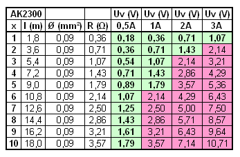
Standard full wired male to female 'extension' RS232 cables are allowed, but up to a certain limit. (e.g.: Reichelt AK2300)
It is never experienced how many can be used, but a few do not disturb the communication.
This type of cable is by far not able to conduct the full 3 Amp of the GCA85 and GCA101!

The conductor cross-section of the AK2300 by only 0.09 mm ² per contact limited the max. number and the max. current.
The table below shows the number (x) of the max. cascadable AK2300 for 0.5, 1, 2 and 3 Amp.
Here, a voltage loss Uv = 2 Volt is tolerated and + and - are using 2 contacts in parallel.
If only 3 or 2 contacts, instead of using a total of 4 contacts, reducing the number (x) of the max. cascadable AK2300 to 3/4 or 1/2 of the table value.
Connection cable GCA50 / CAN-GC2 <> Interface
PSK header connectors
IMPORTANT NOTE !!!!!!
Some users seem to know better, and solder wires directly to the pins or the pc-board.!
That is totally unacceptable !!
Wires will easily break off, and cause a lot of damage in many cases.
So use connectors !!!!!
In order to ease making these cables, it is also possible to buy the necessary tool, to create the PSK cables.
The best wire to be used with PSK connectors is 0,25 mm². (AWG 23)
This special plier will be sold for net price of € 18,25 if ordered together with complete kits. 
Just ask Peter
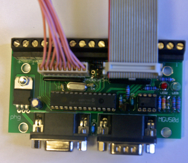
Two possible options can be used for this connection. (see picture below)
Option 1 (left on picture)
This cable should be made with wire 0,25mm.
| Qty | Materials | supplier |
|---|---|---|
| 2 | PSK254/10W | www.reichelt.de |
| 1 | PSK-Kontakte (set of 20 pcs) | www.reichelt.de |
| 1 | Psk-Crimpzange | www.reichelt.de |
Attention!:
Wires are NOT crossed or mirrored i.e. connect pt 1 to pt 1 , etc.
Option 2 (right on picture)
Flatcable 10x2 + connectors. The side without the notch will fit easily.
| Qty | Materials | supplier |
|---|---|---|
| 2 | PFL 20 | www.reichelt.de |
| 1 | Flatcable AWG 28-20G 3M | www.reichelt.de |
| 1 | Crimpzange MWZ 214 | www.reichelt.de |
Attention!:
Wires are NOT crossed i.e. connect pt 1 to pt 1 , etc.
Both options are used here
Direct connection of LED's
 | 1 Epoxyhars lense 2 wire connection 3 Reflector 4 semiconductor crystal 5 + 6 ( = 7 ) frame 8 flat side on Epoxy housing A Anode B Cathode |
| picure from wikipedia.org/wiki/led |
Leds can be connected directly to GCA50 / CAN-GC2 / BS-1 / GCA_PI02 / GCA_LM2
But each LED should also be connected in serial with a resistor.
What should be the value of this resistor?
Each of the output ports of units as mentioned above switches between 0 and 5V.
If we connect one Led in serial with a resistor, the total current through this set-up will be equal in both (resistor and Led).
I.e. when the given voltage of a Led = 2V, the voltage over the resistor will be 5V-2V = 3V.
Following late mister Ohm and assuming that the desired current should be 20 mA (= 0,02 Amp) then the resistor should be 3V / 0,02 Amp = 150 Ohm.
Different Led colours have different Voltages but mostly never more than appr. 3.5 Volt.
The normal maximum current in a standard Led is 20 mA (= 0.02 Amp), but that could be too much of intensity for this purpose.
The current through the Led determines the brightness, but of course that is also very much depending on the type of led.
Suppose we need a current of 10 mA (= 0.01 Amp). That usually will be more that sufficient.
* LED Red and Yellow : Ledvoltage appr. 2V so resistor Voltage should be 3V / 0.01 A = appr. 330 Ohm
* LED Green : LedVoltage appr. 3V so resistor Voltage should be 2V / 0.01 A = appr. 220 Ohm
* LED Blue and White : LedVoltage appr. 3,5 V so resistor Voltage should be 1.5 V / 0.01 A = appr. 150 Ohm
These values are not very critical.
Each port of PIC Chip on Microchip microprocessors can supply 25 mA, but the total sum of the currents should not exceed 200 mA (0,2 Amp).
With the given situation, giving each led no more than 10 mA (= 0,01 Amp), there is no danger to go that far.
Leds (with the serial resistor ALWAYS connected), can be used in the following ways :
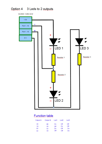
 |  |  | GCA50 connection list CAN-GC2 connection list |
| two ways to connect single Led works with: GCA50(0)(a) CAN-GC2(a) GCA_PI02 WIO_xx | Two leds with 1 output works with: GCA50(0)(a) CAN-GC2(a) GCA_PI02 WIO_xx | Three leds with two outputs works with: GCA50(0)(a) CAN-GC2(a) GCA_PI02 WIO_xx |


