CAN-GC12 CBUS switch panel
Introduction
This unit is identical to the GCA123, but now for use with CBUS.
The popularity of using your Android or iPhone for controlling turnouts is growing.
But still I hear people who are opposed to it, because it is mostly not a single handed easy to use device.
For example the CAN-GC5 or RocoMaus are confortable for controlling a train, but commanding switches need always the
information about he address of the turnout to be commanded.
This unit can sometimes be of a better help.
Specially for testing turnouts, or manually fiddling around with trains over a few turnouts, this unit CAN be extremely useful.
The outside look is virtually the same as the GCA123, fitting in the same box.
Programming is done in the same way as for CAN-GC2(a).
Also a nice front panel is available now, which also fits the GCA123.
Standard, the front plate indicates 8 Switches, left for straigh position, and right for turn.
But with specal configuration in the turnout, it is possible to control 16 turnouts.
Assembling instructions
A few remarks have to be made to help you being succesfull with the production of this unit.
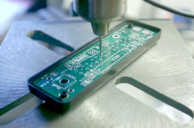
Picture shows different pcboard but the idea is exactly the same.
Fix the empty PCB with screws in it's future housing, and use it to drill the exact positions of the pushbuttons and leds.
 Use the pcb as a mould for holes of pushbuttons and leds.
Pushbutton and led positions have a little center hole for this purpose.
All other parts can be mounted after that.
The pushbuttons and leds are mounted at the backside of the PCB.
Please take care not to use the center hole of the leds for soldering, because that one is only a drilling mould.
After a serious check, connect the pcb , without IC's inserted, to CBUS. Check if 5 volt is correct between pt 8 and 20 in IC1 socket.
CAN-GC12 will announce itself in programming the CANBUS as a CAN_GC2, because it is internally the same thing.
Hardware
Confuguration for commanding turnouts / signals
A turnout can have the same adress in CBUS as the pushbutton to command it.
If you program the address (or adresses when it is coil driven motor) the same as the turnout.
It will work fine that way, but these buttons are now not noticed by Rocview, so the visible position on screen will not change.
That is Ok, if you are not running Rocview, but it is very inconvenient when Rocview is there and shows wrong positions.\
To overcome that issue, start using virtual address(es).
The simplest way is use adresses that are far out of the range you are using.
For example you use addresses 1-100 for your turnouts, use 1101-1100 as virtual addresses.
You are rather free to choose any number, up until 9999. ( maybe even further, I never tried).
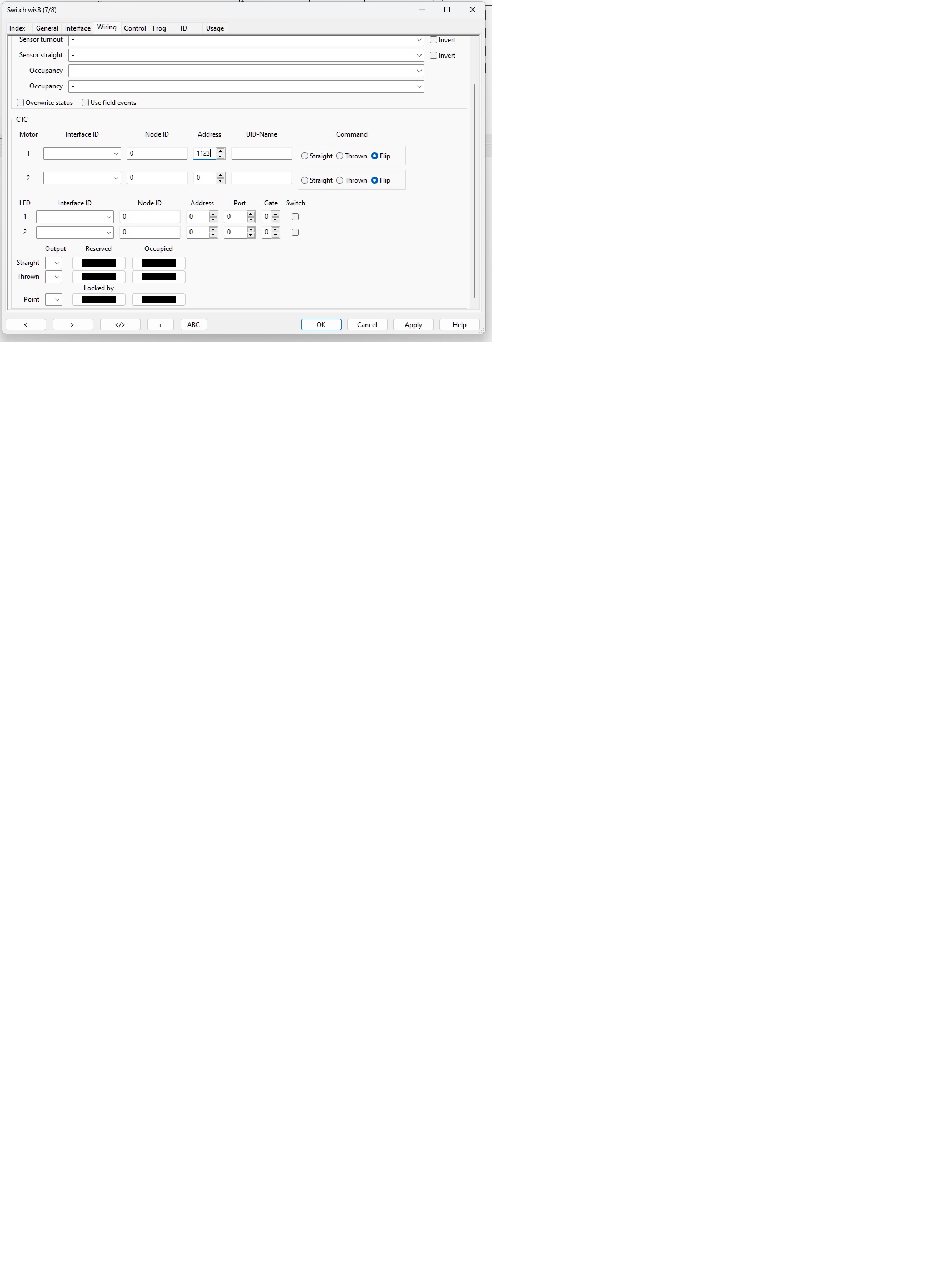
Now you have to enter these addresses (here in example address 1123) in CTC area of the wiring popup page like shown below.
This example shows the seup for a servodrive with CAN-GC6.
For commanding coil drive use two adresses, unmark command 'FLIP' and mark resp. 'STRAIGHT" or 'THROWN'.


