Table of Contents
EXAMPLE and USE of a Rocrail ACTION: Railway Level Crossing.
Introduction.
In order to document and describe the use of Rocrail “Actions” together with their Initiator and the required “Output” the example of a railway level crossing gate operation is given.
In Rocrail the following are required to be set-up:
- What output is required to operate the activity? Rocrail “Outputs”
- Under what conditions is the activity operated? Rocrail “Actions”
- What initiators create the conditions for the action? Rocrail “Sensors”
The Sensors determine if the Action should be processed, that then operates the Outputs.
The following figure shows the situation.
A single track/train direction level crossing has gates that need to be closed before the train arrives and need to be opened after the train has passed.
In order to set this up using the Rocrail tools the following procedure can be followed.
First: The Required Activity. “Output”
What is required to happen? What needs to occur and how is this to be actuated are the questions that need to be answered and set-up in Rocrail.
Examples are: Lights to be turned on. A horn needs to sound. A message is to be announced or:
In this example the activity is: - opening and closing of the crossing gates.
Since the crossing is servo operated there are in fact TWO activities.
- Close the gates and
- Open the gates.
In the case of a powered solenoid operated crossing only one activity is needed – Close the gates. Since if the solenoid is de-energized the gates will open by themselves.
We now need to set-up HOW the activity is operated (actuated). What OUTPUT is required to have the activity operated.
Rocrail Output Set-up:
A Rocrail “output” per the Output Tables can operate only one physical output, eg only either the Red or the Green output of a typical decoder address. This output is either on, or off.
So in the case of the level crossing the RED output of a decoder address can be used to CLOSE the gates. The GREEN output can be used to OPEN the gates.
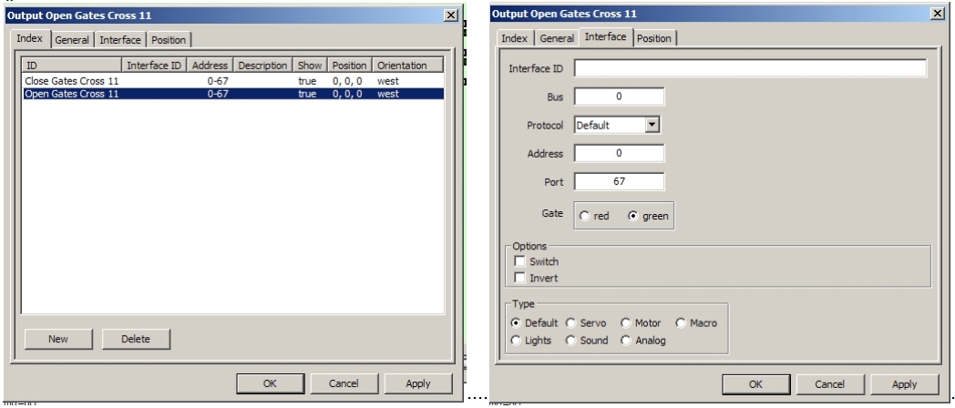
This set-up needs to be configured in the Rocrail Output Table per below figures:
The Two Outputs are created in the Output Table. ———– Each output is connected to the physical output. (67 R or G)
Once the output(s) has been defined the Action can be defined that operates on the output(s).
Second: What is the Action required?
The output has been defined and now an Action can be created that operates on the output(s).
In this example the Actions are:
- Close the crossing gates.
- Open the crossing gates.
In Rocrail the Actions table can now be configured.
The example figures:
The Two actions Open/Close are created. Each uses one of the ALREADY created Outputs. In this example each Output can be “on” or “off”. For a solenoid for example on “on” energizes the output and the off de-energizes the output.
In this servo driven case the “Gates Close” action operates the RED output “on”. The gates close. The “Gates Open” action operates the GREEN output “on”. The gates open.
So there are now:
- two outputs in the Output Table and
- two actions in the Actions Table.
The question now remains: When is the action(s) to be activated?
Third. Initiation of the Actions.
The questions are:
- When are the gates to be closed?
- When are the gates to be opened?
“When” in this sense is related to the hardware set-up of the layout. Going back to the first figure of the situation there is a Sensor numbered 73 that can be used to close the gates and a sensor 74 behind the crossing, that can be used to open the gates.
See the situation below:
If sensor 73 is connected to the CLOSE action, then the gates will close (and remain closed – servo) if the sensor is activated.
Using the “Properties” menu of sensor 73 the “Actions” button can be used to bring up the “Action Control” window. By selecting the action “Gates Closed” from the ID list, the action can be attached to the sensor. Finally the STATE of the sensor is given – “on”. Sensor “On” means CALL the action – eg close the gates,
So now if Sensor 73 is activated, Action - Gates Close will be called and this operates Output - Close Gates containing the physical output 67-RED, that operates the servo in the close direction.
In the case of this level crossing, the gates will also need to be opened, after the train has passed.
In the example Sensor 74 behind the crossing can be used.
See the figure.
In this example, sensor 74 is connected to the TWO actions, Close and Open. If sensor 74 is active then train axles are still near the crossing and the gates need to remain closed. This is a safety action, - maintaining the gates closed, although not really required. If 74 is “on” then close the gates (eg Keep them closed!)
The SECOND action attached to the sensor is for the sensor “OFF” state. Two actions can always be attached to a sensor – one for the “on” state and one for the “off” state.
If the Sensor goes “Off” then the Gates “Open” Action can be called that operates the Open Gates Output that sets the physical output 67 GREEN – that operates the Open direction of the servo.
In this case the assumption is that the sensor 74 off state, represents the fact that the train has FULLY passed. Eg this assumes that all axles can operate the sensors.
CONCLUSION:
This level crossing example attempts to describe the way Rocrail's Outputs/Actions/Sensors (tables) work together per the design.


