maerklin_6015_6017-en
Marklin 6015/6017
Description
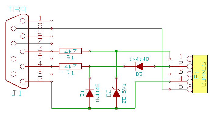
You need to solder a small circuit to set the signal levels to 5V instead of the 12V which are provided by the serial port. If you use a 6015 Booster, the pin 1 of the BoosterBus plug is on the left side (if you look at the front side of the plug). Pin1 of the BoosterBus plug of 6017 Booster is on the right side. A DB9 connector is used in the circuit diagram below. If you use a DB25 connector you have to solder the cables as shown in the table:
| DB9 | DB25 | |
| Signal | Pin | Pin |
| TXD | 3 | 2 |
| DTR | 4 | 20 |
| DSR | 6 | 6 |
| GND | 5 | 7 |
Circuit Diagram
maerklin_6015_6017-en.txt · Last modified: 2018/11/12 08:56 by 127.0.0.1
