Table of Contents
MGV105 DDX booster
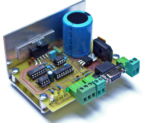
The assembled prototype
Description
The ORD-1 is a well known solution to run the DDX driver inside Rocrail for direct control to the rails. Ord-1 includes also S88 bus connections. MGv105 has no S88 bus, because in the MGV family of circuits, we use Loconet instead of S88.
This DDX booster is powerfull with 3A output. It is a booster because it uses only one DC circuit to make full swinging output.
A small processor will sense short circuit, and will be able to shut down the power directly.
Also Rocrail DDX is still able to control power on/off.
When USB-RS232 converter is used, the feed-back for power on/off is not supported.
For that purpose, two extra outputs are available to connect to Loconet.
The program in the PIC12F675 is only a few lines. After a short circuit has been detected, the PIC will shut off the output, and make LED4 keep flashing. Only after Rocrail (or others) shuts down the rail output, it is possible te restart.
Rocrail will handle (if outputs from J3 are connected to loconet) that a short circuit has occurred.
The program in processor is written with PicSimulator IDE from www.oshonsoft.com
Features
- Powerful 3A output with standard single 16V transformer.
- Internal short circuit detection shuts off output.
- Opto-coupler isolated connection from rails to PC.
- Seperate output to Loconet-Rocrail for short circuit detection and rail power off.
- Separate short circuit indication in Rocrail.
- Flashing LED when short circuit occurs.
- Supports DCC and Motorola.
The Files.
| mgv105_sch.pdf | The schematics |
| mgv105_pcb.pdf | The pcb layout |
| mgv105-complist.pdf | Components list |
| mgv105-dwg.pdf | Connection diagram |
| MGV105.bas | BASIC source of firmware |
| MGV105.hex | compiled firmware |
Important remarks
- The transformer should be 16Vac and at least 50VA to meet the power demands of MGV105
- Serious efforts have been made to make this unit suitable for do it yourself.
However no responsability for what ever reason can be taken by the writer of this article. - Never connect the used transformer to any other items, it must be absoltely dedicated!
- The picture shows the build prototype. For cooling a simple 100x140x1,5mm aluminium plate is used. This cooling is suitable up to approx 1,5A.
- For higher continues power, addional cooling of 1,8 K/W is advised. (like Reichelt V7331E).

- There is some misunderstanding about boosters. Practically spoken, a booster is a unit that makes a positive and negative signal out of one DCC voltage. This means that real boosters do not have one of the output lines connected to ground.
This is important to know, specially because it demands a dedicated transformer, and NO ground wires connected from one transformer to another.

