Table of Contents
Tracks
Representation
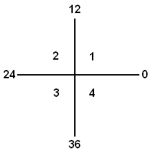
The turntable has 48 steps of 7.5°. The connected tracks are numbered counter-clockwise from 0 to 47.
The track 0 is the 0° of the first quadrant. This is the representation of the turntable in Rocvew, if the orientation is set on "West" (Standard).
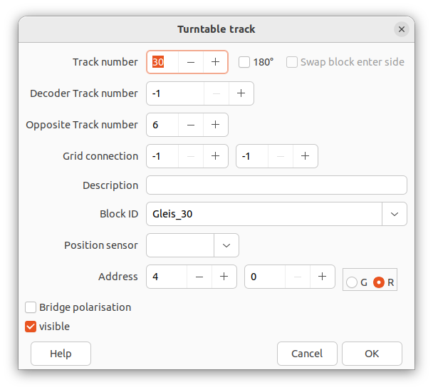
Turntable Dialog Tracks Tab.

Overview of the defined connected tracks to this turntable.
A red background of the track cell means it is invisible.
Add a Track
180°
Only for the control of a trun table with the interface type generic.
If this option is activated, the track number is displayed as 180 in the overview.
The decoder address for the 180° rotation is stored here.
If a feedback is entered, the rotation will only be carried out if it is active.
Swap block enter side
Only in combination with 180°, is used to control a rotary traverser in the automatic system. If the 180° rotate command is sent from the traverser object, the platform rotates and the block enterside is swapped so that the locomotive drives in the correct direction after the rotation.
Track number
The wanted track number to define which must range between 0 and 47.
The track number represents the position of the bridge inside the tt symbol when the requested position is reached, without any other impact.
It is recommended to draw the tracks to be connected to the tt first and then align the bridge position by the track number to fit to the connected track best.
Decoder Track number

Example
Assuming a turntable decoder type with 24 tracks equally arranged:
| Track | Decoder track |
|---|---|
| 0 | 1 |
| 2 | 2 |
| 4 | 3 |
| 6 | 4 |
| … | |
| 44 | 23 |
| 46 | 24 |
Opposite Track number
An optional track for the 180° turn option.(For multiport type only.)
Leave at -1 if not needed. (Or equals to the Track number.)
Note: This information is required if also wanted to travel to / from the minus side of the bridge track ("green") from / to the connected track
and the therefore necessary routes are to be generated by the Track block management.
Grid connection
Generates a graphic connection from the track to a specific coordinate on the edges of the turntable symbol.
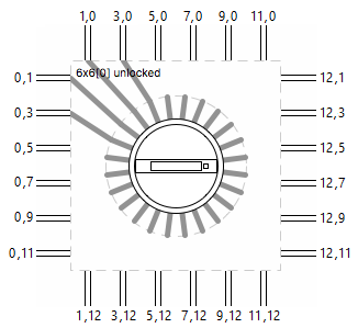
The left upper corner of the turntable object is defined with the grid coordinates X="0" und Y="0", if the turntable object is in default orientation "west" located. Rotating the turntable object rotates the reference point of the coordinates as well.
Grid maximum
The right-lower corner grid coordinates are double of the turntable size.
If for example the turntable symbolsize is set to 5, then x="10" and y="10" represents the max. grid point.
Therefore connecting objects (usually tracks) are always connected to odd grid coordinates.
The XY coordinate units are 0.5 grids.
The general option Grid connection must be enabled.
In this example, with a symbol size of 6, 4 tracks have a grid connection defined: (15, 17, 19, 21)


User example
BlockID
Block ID used for generating routes between bridge and tracks in case the manager is activated.
Description
Free text for display only.
Position sensor
Sensors should be placed at every connected track to detect the bridge position.
It is valid when a sensors is high and will be shown as detected in the track plan.
Check the turntable type for details.
Address
When using the "generic" interface type, the address for the desired track target position is entered here.
Bridge polarization
Set the polarization of the bridge for entering this track.
Visible
Show this track. Disable if it is only for the 180° turn option without any real tracks connected.


