Table of Contents
Modular Layout Setup
Requirements
- File system knowledge
- Experienced Rocrail user
How to proceed
- Create module files.
- Start the server with an empty module plan.
- Insert the singel modules in the module plan.
- Setup the module connections.
- Restart.
Definition of a module
Modules must be created with Rocview in offline mode, no server connection, and saved with its own unique file name.
If one or more modules are part of one none changeable section, like a railway station, they should be defined in Rocrail as one logical module.
Symbol prefix
Every module must have its own unique object IDs, so a symbol prefix must be set in the properties before adding objects:

Module sides
All modules have four logical sides named by the main compass points:
- North
- West
- South
- East
Module routes
A module route generally have a compass point and a block, but if there is no block in between it will have 2 compass points.
It is preferred to manually define Module routes if extra flexibility is needed. Direction arrows are not necessary but visually helpfull.
This step can be skipped if no extra flexibility is needed, and leave route generation to the Router.


Each module side may have up to 5 track connections.
Module routes are automatically resolved after they are part of an arrangement. (Module plan.)
Example


Trains will only run on the right side with the following routes:
| From block | To block | Crossing blocks | Commands |
|---|---|---|---|
| point-ws | 3b2 | - | 3t2=straight |
| 3b2 | point-es | - | 3t2=straight |
| point-en | 3b1 | - | 3t1=straight |
| 3b1 | point-wn | - | 3t1=straight |
| point-en | point-ws | 3b1, 3b2 | 3t1=turnout, 3t2=turnout |
Create an empty module plan
- Open a new empty Workspace with Rocview.
- Open the Rocrail Properties General tab.
- Change "plan.xml" in a none existing file like "modules.xml". Using the default "plan.xml" will not work because it already exists.
- Select Type Module plan.
- Restart the new Workspace.
Modular Track Layout
After restarting the Workspace an empty Modular Track Layout has been created:

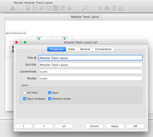
With a right click on the empty layout the properties can be viewed and changed of the Module plan.
Title
Free text for the arrangement title.
This text will be shown in the titlebar of Rocview.
Sub title
The sub title will be used as label for the modular layout panel.
Locomotives
The XML file containing all locomotives properties.
Default: lc.xml
Routes
Routes XML file, default rt.xml.
The following module independent objects are saved and loaded in/from the routes file:
- Global routes
- Schedules
- Actions
- Locations
- Boosters
- Variables
- Decoders
- Tours
- Waybills
- Links
- System
- Weather
- MVTrack
Init field
Flip all switches and signals at startup to get defined positions.
Save modules
Allow saving the module files.
Save
Allow saving the moduleplan file.
Modules routes
Use routes defined in the modules.
Adding modules to the plan
Right click on the empty Modular Plan and select Add module:

Select a module with the File Chooser and set the module its ID.
After that the module is loaded and shown in the Modular Plan:

Moving and Rotating
First the edit mode must be activated: Menu → Track plan → Edit module plan
The module can be dragged around with the mouse on an empty grid cell.
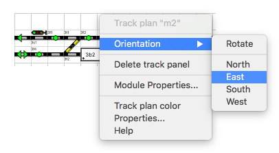
With a right mouse click on an empty module grid cell a popup menu will appear:

Select the wanted orientation for this module.
Colors in Module plans
For setup of colors in Module plans see here: Track plan color
Removing a module
A right mouse click on an empty grid cell of the module to be removed and select Delete track panel in the popup menu will removing it from the module plan.
| The module will only removed from this arrangement. The xml-file of this module will not deleted  |
Module properties
Title
Free text for the module title; Must be set unique because it is used for removing modules.
ID
Module ID which is a reference for all other modular actions. Be carefull to change this ID because it could make the module routes invalid.
Number
The number is used for graphical representation, location, in the RocNetNode Dialog.
File
XML File with the module definition.
X, Y
Module position in the arrangement.
Rotation
Which side of the module will be upper most is selected by the rotation option:
- North = 0° (equals the module without rotation)
- East = 90°
- South = 180°
- West = 270°
Module connections
After adding one or more modules to the plan the module connections can be set.
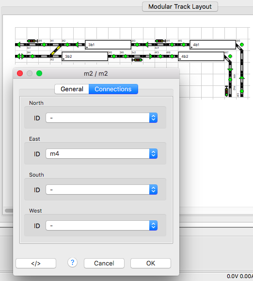
With a right mouse click on an empty module grid cell select Module properties from the popup menu and switch to the Connections tab:

The left module in this example has the ID m2 and the right one m4.
The module connections for the left module, m2, is on the east side m4.
The module connections for the right module, m4, is on the west side m2.
Rotated modules
In this example the left module is rotated and its South side is on top:

The module connections for the left module, m2, is on the WEST side m12.
The module connections for the right module, m12, is on the WEST side m2.
Rotated view of the module plan
Right-clicking in the module-free area opens the context menu.
From Rev. 5523 the orientation of the hole module plan can be rotated by 0 / 90 / 180 / 270 degrees.
The rotated orientation only applies during the current session and is not saved.


