Table of Contents
RocNetNode Pi08 LEDs


![]()
![]()
![]() Content → Command Stations → RocNet
Content → Command Stations → RocNet
-
-
- GCA-Pi01 | GCA-Pi02 | GCA-PI03 | GCA-PI04 | GCA-Pi05 | GCA-Pi06 | GCA-PI07 | GCA107 Relay board | RocDisplay | Fast Clock | LED driver Pi08
Introduction
The Pi08 is based on the PCA9622 16 bit I2C LED driver.
I2C Addressing
The final Pi08 will be addressable in the range from 0x60 to 0x6F for driving 256 separate LED outputs connected to one RocNetNode/Raspberry Pi.
Chip Mode
The PCA9622 must be programmed after every system power on.
RocNetNode will scan this I2C range at startup or after using the RocNetNode Dialog and will setup the found chips.
The following registers will be set automatically:
- In MODE1 the SLEEP register must be set to normal mode. (To activate the PWM oscillator)
- Register LEDOUT0…LEDOUT3 must be set to enable the LED driver outputs.
Connecting LEDs
The LED common is the anode(+)(long leg) on +5V J1 and J2 pin 1.
Output support
| Parameter | Description |
|---|---|
| Port type | LED |
| Addressing | FLAT from 1 to 256 |
| Value | The on PWM from 0 to 255 |
| Parameter Off | The off PWM from 0 to 255 |
| Blink | Supported with regarding the delay value. |
| Delay(Dimming) | Used as increment. A value of zero will switch directly to on/off PWM. A value of one ist the slowest dim, app. 10ms * (on-off) PWM. (Increasing the delay value every 10ms.) |
Note: The dimming speed could be influenced by the number of LEDs which have to be set at the same time.
Signal support
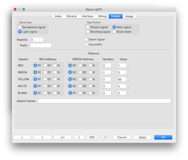
This is both for simple and medium complex signals up to 8 LED and max. 10 aspects. For more complex signals the macro type should be used.
Only the RED address will be used as offset for all LEDs.
| Parameter | Description |
|---|---|
| Control | Aspect numbers |
| Port type | LED |
| Addressing | FLAT from 1 to 256 - number of aspects |
| Delay(Dimming) | Is set automatically set to 10 so the LEDs will slow dim on and off. This value is fixed and cannot be changed in the signal properties. |
Aspect Values
See: Aspect Values
The number of controlled LEDs will be calculated from the aspect values.
Example
- Bus 2: Node ID 2
- Base address 5
- Control: Aspect numbers
- Port type: LED
- Aspects: 3
Aspect values:
| Aspect | Value | Hex | LED address |
|---|---|---|---|
| 0 | 1 | 0x0001 | 5 |
| 1 | 2 | 0x0002 | 6 |
| 2 | 1285 | 0x0505 | 5 + 7 (blink) |
Aspect value examples
| Value | LEDs |
|---|---|
| 0x0001 | LED 1 on |
| 0x0002 | LED 2 on |
| 0x0004 | LED 3 on |
| 0x0008 | LED 4 on |
| 0x0101 | LED 1 blinking |
| 0x0505 | LED 1 and 3 blinking |
| 0x0003 | LED 2 and LED 1 on |
| 0x0103 | LED 2 on and LED 1 blinking |
| 0xFFFF | All LED's Off |
Brightness
There are 3 brightness modes available:
| Mode | Description | Activation |
|---|---|---|
| Weather | The brightness reported with the clock update events is used. | Default. With a LED output on address 1001. |
| Day | The brightness is set by output command. | With a LED output on address 1002, the output value is used. (If zero: 255) |
| Night | The brightness is set by output command. | With a LED output on address 1003, the output value is used. (If zero: 100) |
Macro support
The LED Type is also supported in the macro setup.


