Table of Contents
GCA124 FREDI
NOTE This unit is replaced by GCA124-8
See GCA134-8
The GCA124
Description
This hand held throttle is very well supported in Rocrail.
For a small fee Fred Jansen is prepared to program an Atmega8L for you.
The Hardware
| The schematics |
| The PCB design |
| User manual |
| N.B. Only complete ordered kits will be supported! |
|---|
The bill of materials (GCA124 V1.5)
| Qty | Reference | Description | order nr |
|---|---|---|---|
| 2 | R1,R2 | 12 Ω | |
| 3 | R4,R6,R32 | 47 KΩ | |
| 1 | R5 | 100 KΩ | |
| 1 | R7 | 2.2 KΩ | |
| 3 | R8,R9,R12 | 470 Ω | |
| 1 | R10 | 4.7 KΩ | |
| 1 | R11 | 10 MΩ | see assembling info |
| 1 | R13 | 68 Ω | |
| 1 | R31 | 82 KΩ | |
| 1 | C1 | ELCO 22 uF 25 V radial | |
| 5 | C4,C5,C10,C11,C13 | 100 nF | |
| 1 | C6 | 47 pF | |
| 1 | C7 | ELCO 10 uF 25V radial | |
| 1 | C12 | 1 nF | |
| 2 | C2,C3 | 15 pF | |
| 1 | C8 | 10 nF | |
| 2 | Led1,Led2 | LED 3mm green | |
| 1 | Led3 | LED 3mm red | |
| 3 | D1,D2,D3 | DIODE BAT85 | |
| 1 | T2 | BC337-40 | |
| 1 | IC1 | ATMEGA8L8 | |
| 1 | IC1 socket | Dil-28 small | |
| 1 | VR1 | TS2950 CT33 | |
| 1 | J1 | Socket RJ12 6PC | SMD type |
| 1 | S2 | Encoder EC11 with push switch | Darisus EC11E15244 |
| 6 | S3,S4,S5,S6,S7,S8 | Tact switch PC horizontal | Reichelt 3301b |
| 1 | Q2 | CRYSTAL 7,3728Mhz | |
| 1 | ICSP1 | header 2x3 | |
| 1 | Box | Housing | Reichelt SP 2090 SW |
| 4 | self tapping screws | 2,9 x 6 | Reichelt SBL 2965 |
| 1 | knob | ||
| 1 | cable RJ12 |
Assembling instructions
A few remarks have to be made to help you being succesfull with the production of this FredI.
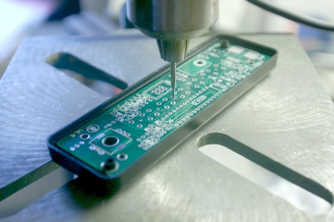
Fix the empty PCB with screws in it's future housing, and use it to drill the exact positions of the pushbuttons, SW2 and leds.
 Use the pcb as a mould for holes of pushbuttons, leds and SW2.
Pushbutton positions have a little center hole for this purpose.
All other parts can be mounted after that.
The pushbuttons and leds are mounted at the backside of the PCB.
Please take care not to use the center hole of the leds, because that one is only a drilling mould.
After a serious check, connect the pcb , without IC1, to LocoNet. Check if 3,3 volt is correct between pt 7 and 8 in IC1 socket.
As far as my experience has gone, R11 can be omitted.
Should you have any misfunctioning, the resistor might help.
Then refer to installation instructions at http://fremodcc.sourceforge.net/diy/fred2/fredi_d.html
If you can not find it there, contact Peter.
Testing before inserting IC1.
After assembling the pcboard, it is better to test the 3,3 Volt power to the processor, before inserting the processor itself.
Just connect GCA124 to LocoNet and switch Railpower ON.(Important!)
Between point 7 & 8 of IC1 should now show 3,3Volt.
Short startup instructions
- Insert chip, and connect GCA124 to LocoNet.
- Three leds will show slow running lights.
- Be sure to have power On in LocoNet.
- Press all, buttons sequently, including pressing and turning speed knob.
- If that all goes well, the FredI will respond with leds in fast running light.
- Disconnect GCA124, and reconnect again.
- Now red led is lit.
- Prepare a loc in Rocrail for dispatching. See below: Rocrail and the FREDI
- Press shift button (bottom one) and speed knob together.
- Green led will be on, you've succeeded.
Rocrail and the FREDI
- For setting up a Fredi in Rocrail look at: setting up a LocoNet Slotserver
- Leave the Interface ID in the loc setup empty: LocDialog Interface Tab
- Fill in the LC IID and the DP IID in the : Rocrail general Tab
- Fill in the IID of the Command Station that controls the locs (LC IID) : Loconet Interface Tab
- Check the: Use mode column for dispatch
- Tell the desired loc to dispatch, look at : Throttles


