Table of Contents
GCA145 Turntable / Fiddle yard controller
Description
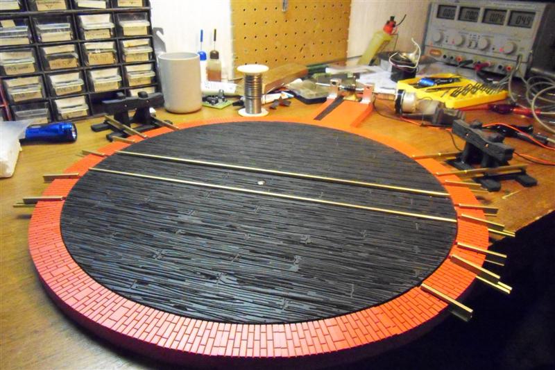
Using a stepper motor seems to be the most simple way of moving a turntable or fiddle yard to the desired position.
And because mostly all of us will have one or more stepmotors available from any old printer/scanner/ disk-drive, we have to deal with a wide variety.
And if there are no motors available, still a wide variety of these motors are available from Conrad, Reichelt, Pollin, Rapid, etc.
The needed power for a turntable can be rather low, but a fiddle yard needs a more powerful engine to be able to move it.
This unit provides enough energy for most common kind of motors.
The best suitable motor is the one with four wires (two coils).
The output voltage is adjustable over a wide range, to adapt to the chosen motor.
The position setting can be done by an incrimental switch , as known from many train speed controllers,
or by means of the input connector J5.
This connector can be straight connected to any GCA I/O decoder, like GCA50(a), GCA53, GCA500, CAN-GC2, GCA_PI01, or various WIO units.
With this last option, feed-back is not possible, so that should be established in other ways.
Also a fairly simple DCC- or Motorola Decoder GCA174 can be used, to be able to control straight from digital rails.
You are free to create your own solution to fix motor to the TT/fiddle-yard.
The bottom of these pages show a few examples, about how satisfied users have been constructing their solutions.
48 positions are available and each position is set by a number of steps counted from 1 to 48.
Each step can be programmed, using a simple menu and the addional GCA146 control and display board.
The total control unit is rather complicated, yet, through the use of a good worked out pcboard, it is rather simple to construct.
Boards and /or complete parts sets are available.. Ask Peter.
The rails on the TT will be polarised according to the position. This position is also programmable.
The maximum amount of positions and all other settings are accessable by means of GCA146.
In this case, also in manual control, you do not have to worry about polarisation, it is always correct.
For fiddle yard, no change in polarity is necessary, but it is nice that power of rails will be switched off during movement.
If you have any ready made turntable like Fleischmann, Maerklin, Roco or anything else, this unit is also useable but:
like in selfmade turntables, you wil have to make a connection between stepper motor and turning part of your item.
Further in these pages you will find some examples how a mechanical solution can be made.
You made your own nice design? we are happy to publish it here for the benefit of other TT lovers.
Also an extra setting is available to enable a correct position when there is still some free-space movement in the driving set.
The software runs a previous amount of steps further (only in forward direction), and then runs this amount of steps backwards.
These steps can be set fom 0 to max 99.
The program also is able to 'ramp-up'and 'ramp-down'.
This will give a rather real movement.
Both speeds, maximum and minimum, have their own set-point, as well as the incremental speed.
Please refer to manual for more info.
The final result
Previous version MGV145
Many enthousistic users made it necessary to start a new charge of MGV145, resulting in GC145.
Though firmware is full 100% compatible between two boards, the GCA145 has all the extra changes, as stated in MGV145 all on-board now.
* MGV145 The previous board description
Manual
All info about connections and use of the GCA145 will be found in these manuals.
Power
For the right choive of transformer, please refer to this table.
This board has the possibility to control stepmotors up to 24V, 2 Amp.
The demand of the maximum current is mostly depending of the type of steppermotor which is used.
The maximum current is adjustable.
Entering the power Through J1(1+2), a multifuse will limit short circuit problems, if any.
A 6A rectifier bridge is capable of handling up to the maximum current given by VR1.
VR1 is a switching mode power supply, which means that there is much less energy generated in VR1, compared to normal linear regulators.
Many types of steppermotors will require a variety of different voltage to supply to the motor.
VR1 is adjustable by means of P1, in a range from 5.2 to 24Volt (if sufficient Power is supplied to the board.
This will cover mostly all of the available motors.
For more info about adaption to the used motor, please refer to the manual.
VR2 is regulating 5V for the logic on board ,and the relays K1 and K2.
The two regulators and U3 (the power output), are mounted to a cooling device.
The picture shows a cooling , suitable for allmost all situations.
However, if it comes to a situation where a stronger motor is used in a more constant movement, the cooling can be replaced by a larger type. (see parts list), or a little fan will also be suitable.
The logic control
When write line goes high, the processor will make ´pos match´ high, shut off both relays, reads PortA and starts running to the position given.
This write line respond can be disabled in version N_V3.4 or higher by setting menue 1.6 to 0. It will make GCA145 respond to any change in command byte via J5.
After the postion has been reached, ´Pos match´will be forced low, to signal the LocoNet, that TT/FY is stable in position.
Also depending on the position, the correct relay will be switched on, to give power to the rail on the bridge.
Reverse or not of the railpower is depending on the chosen control type (see settings).
The amount of steps of the required position is read from EEprom, and then calculated in respect to actual position.
For the TT with connected wires counts, that there should be a balance of the amount of turns right and left, to avoid that cable to the bridge will be too far twisted.
Controller will normally calculate and take the shortest way, unless this ´twist´ is telling otherwise.
The control of stepper-motor is done by U2 and U3.
This combination of stepper control chips is making life easier for the microprocessor, which only have to give direction and clock.
All control of the motor, including an adjustable maximum load, is made by these control chips.
The diodes at the output of U3 are made to suppress distorsion of the motor. Diodes are special high frequency types, to give best performance.
The eep jumper is no longer of any use.
Unused bits >> Important:
It is not always necessary to use all 6 command bits.
If -for example- there are only 11 positions in use, bits 0-3 (pins 3..6 of J5) will be OK.
But in that case make sure that unused bits 5 and 6 (pins 7 & 8 of J5) are connected to ground (J5 pin2), NOT left open !!!
The best way is to use a 1 KOhm resistor from each unused pin to ground.
Led functions GCA145 board
| Led# | Function | colour |
|---|---|---|
| Led 1 | 5V OK | green |
| Led 2 | Bridge rail ON (reverse) | yellow |
| Led 3 | Bridge rail ON (forward) | yellow |
| Led 4 | motor running fwd | green |
| Led 5 | motor running rev | red |
| Led 6 | TT ready (J5,pin10 is low) | green |
Position feed-back
The actual feed-back of positions to Rocrail or any other applicable program, has not been a very important issue.
Due to the fact that another 6 lines should have been available, to connect to LocoNet or else, it was skipped.
But it still is possible.
It is not available at present, but if anyone feels the need to have it, please send message to Peter.
Rail power
Rail power from booster/central unit/trafo is needed to power the rails on the bridge and is connected to J1(3+4).
The hardware
The firmware
| Newest firmware is always compatible with all versions Of GCA145 / MGV145 boards. |
|---|
| Hex & basic files VN3.1 |
| Hex & basic files VN3.2 |
| Hex & basic files VN3.4 |
| Hex & basic files VN3.5 |
| Hex & basic files VN3.7 |
Programs as used here are completely written in simple Basic.
The compiler used here, is PicSimulator IDE, a very fast compiler from www.oshonsoft.com.
Remarks on Versions
The firmware for GCA145(or MGV145) has been evaluated in practice by many users.
This made it necessary to change to a different processor PIC16F886, due to higher demands on calculation options and steps.
Motorola or DCC-Control
Basicly, GCA145 is made to be used with GCA50(LocoIo), CAN-GC2(CanBus) or GCA_PI02 (RocNet), aand mNY wioXX UNITS when computer control is desired.
There is also a small interface available to enable digital postion control by DCC or Motorola, straight from the rails.
Three ways are available.
- GCA174 The 6 pin straight position control from GCA50(0) / CAN-GC2 / GCA_PI02 / WIO-xx
- GCA_LM2 The light controller for RS232 solutions. It also useable to control GCA145.
Controlling with Rocrail
The best way to control GCA145 by Rocrail is to select Multiport-Decoder.
Connections to GCA50 / CAN-GC2 / GCA_PI02
IMPORTANT NOTE !!!!!!
Some users seem to know better, and solder wires directly to the pins or the pc-board.!
That is totally unacceptable !!
Wires will easily break off, and cause a lot of damage in many cases.
So use connectors !!!!!
In order to ease making these cables, it is also possible to buy the necessary tool, to create the PSK cables.
This special plier will be sold for net price of € 20,00 if ordered together with complete kits. 
Just ask Peter
Cable to GCA50 / CAN-GC2 / GCA_PI02 / various WIO modules
refer to: **Connection interfaces**
It is possible to use MGV145 / GCA145 without any further connections.
However, the first idea was to use it inside the GCA-LocoNet system, later extended in the same way to CBUS, RocNet and a large number of various WIO modules.
Therefore two connectors are available to interact with a decoder.
Here follows the list of connections, when a GCA50 or CAN-GC2 is used to control.
The cable between the two units is a standard 1 to 1 PSK cable, NO TWISTING !
J5 connections
| connector GCA145 | function | Function |
|---|---|---|
| J5(2) | GND | GND |
| J5(3) | Output switch (no pulse) | position command bit 0 |
| J5(4) | Output switch (no pulse) | position command bit 1 |
| J5(5) | Output switch (no pulse) | position command bit 2 |
| J5(6) | Output switch (no pulse) | position command bit 3 |
| J5(7) | Output switch (no pulse) | position command bit 4 |
| J5(8) | Output switch (no pulse) | position command bit 5 |
| J5(9) | Output switch (no pulse) | New position flag |
| J5(10) | input | Position match |
The position command byte are 6 bits, giving the desired position for the TT/FY to run to.
The write enable is used to tell GCA145 to start.
First the 6 bits are set according position.
To activate the GCA145, write enable should go high.
J6 connections
| connector GCA145 | Setting GCA50 | Function |
|---|---|---|
| J6(2) | GND | GND |
| J6(3) | Block | Feed-back 1st section |
| J6(4) | Block | Feed-back 2nd section |
| J6(5) | Block | Feed-back 3rd section |
| J6(6) | Block | Feed-back 4th section |
| J6(7) | Output switch | Forward sign |
| J6(8) | Output switch | Reverse sign |
| J6(9) | XXX | Not used |
| J6(10) | XXX | Not used |
Rail connection
| Connections of rails on bridge can be done with following list. | |
|---|---|
| GCA(MGV)145 | Function |
| J8(1) | left rail section 1 |
| J8(2) | left rail section 2 |
| J8(3) | left rail section 3 |
| J8(4) | left rail section 4 |
| J8(5) | right rail |
| addional connections | |
| J8(6) | 0V for signal |
| J8(7) | 5V for signal |
| J8(8) | not used |
| J8(9) | reverse side sign |
| J8(10) | forward side sign |
For signs only leds are applicable.
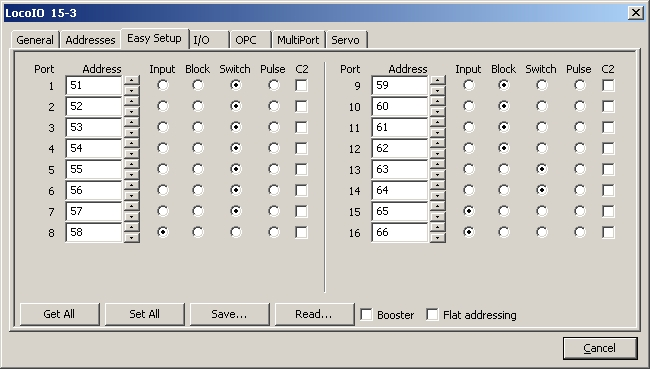
Configuration of GCA50 Turntable or Fiddle yard
Configuration of Rocrail for Turntable
Turntable Dialog
To report the arrival at destination track, a sensor object must added into the track plan.
This sensor need the address from GCA50/CAN-GC2 port 8. (Address 58 in example above)
In Tab "Interface" the ID of this sensor (example "POS") must be set in "Position Sensor".
Also the "Type" must choose as multiport and if necessary, be set the IID of the LocoNet CS into "Interface ID".
The sensors of the turntable bridge be set in "Sensor 1..3".

The settings in Tab "Multiport" comply with the GCA50/CAN-GC2 settings for port 1..7 above.

It's necessary to set the upper Invert option, common for Position Address 0..5.
Otherwise the position command is wrong coded. (GCA145 expect "activ low" signals).
The New Position Flag is default "activ low" and so the Invert option there remains unset.
In Tab "Tracks" the GCA145 stored physical positions of the turntable bridge be mapped to the logical tracks of the turntable object of the track plan.
| The turntable object of the example use 6 of 48 possible positions. The three tracks 45, 0, 3 have the tracks 21, 24, 27 in opposite. | 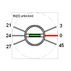 |
The zero-limit switch should be somewhere between positions 45 and 27, which equal position 1 and 6 in the GCA145 firmware
In the example the positions of the tracks are configured as No. 1..6 in the GCA145.
NOTE: GCA145 does not recognise Position 0, positions are possible between 1 and 48.
The mapping must be set, so Rocrail is able to generate the appropriate command to the GCA145 from the logical track number.
In the example:
| Mapping of track numbers | ||||||
|---|---|---|---|---|---|---|
| Rocrail | 45 | 0 | 3 | 21 | 24 | 27 |
| GCA145 | 1 | 2 | 3 | 4 | 5 | 6 |
In the dialog, the mapping looks like this:
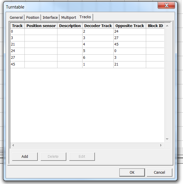
Because the GCA145 uses only one "Position Sensor" to report the arrival for all bridge positions (see New Position Flag' at tab "Interface"'), the individual sensors of the tracks are unnecessary.
Power to the rails
Powering the rails can be done it multiple ways.
But the sledge system with old Märklin wheelsets looked to be the easy way to do it.
On two exhibitions in 2014 (Utrecht.NL and Gangelt.DE) it proofed not reliable enough.
So here is a new idea.
I had a lot of used Omron G2R 12V relays, which were right the ones I needed.
Look in this page for further details.
My design for tt-scale turntable
A new approach for the same task.
A more detailed picture is also available.
The latest version of my design, before I will install it to a N-scale turntable is much more simple and cheaper than the previous one.
Apart from the visible GCA145 and GCA146, most parts come directly from China.
The used motor is a 28BYJ-48 stepper motor with a build in gearing.
That makes to the total steps for one circle on the motor axe up to 4096 steps per circle.
Together with 1:8 belt gearing it will make 32768 steps for one full circle of the TT.
With a TT diameter of 333 mm, each step is approx 0.03 mm!
The power available to the bridge shaft is quite impressive with this very small motor..
An even better result gives a small change in the motor connections.
For that purpose the blue cap should be removed, and the line between the two center points removed.
Net remove the red wire, so only 4 wires are left, and will be connected to the GCA145 point 1..4.
Now, the motor will even produce more power because it is used as a double phase stepper.
Adjust the power on GCA145 to 10 Volt. (see manual how to do that)
My test equipment
Test-setup for GCA145 controller.
The example of the picture above is a simple motor equipped with an extra gear wheel and a matching tooth-belt.
These were just taken out of an old scanner from a neighbour, who thought it had no value at all !!
Tooth-belt is fixed inside-out to a circular triplex disc, which is cut exactly to the right diameter to fit the belt.
What I did is to cut the disc first approximately to the right diameter, and afterwards put it in the drilling machine and use a file to get the exact right size.
Input from satisfied users
If you have designed your own solution for connection stepper motor to bridge, please send pictures.
The new N-scale Fiddle yard by Peter Giling
For my N-demo modules in plexiglass, I created a new fiddle yard with 8 tracks.
Module size (L x W x H) : 750 x 520 x 68 mm.
Track distace (H to H) : 24 mm.
Motor steps between two tracks +/- 2500 steps.
Follow this link: https://youtu.be/EfOiJ_NS3QA
Realized two-step toothed belts drive
 From motor … |  … over a toothed belt … |  … to transmission … |
 … over a 2nd toothed belt … |  … to the bridge axle |  Zero point switch |
| Click on pictures to get a large view | ||
| Documents of mechanics |
|---|
| Complete documentation (german) |
| Parts procurement |
| Video with the setup menue of GCA145/146 and two-step toothed belts drive. |
|---|
| The video shows an obsolete firmware version, but an impression of the features. |
LGB turntable
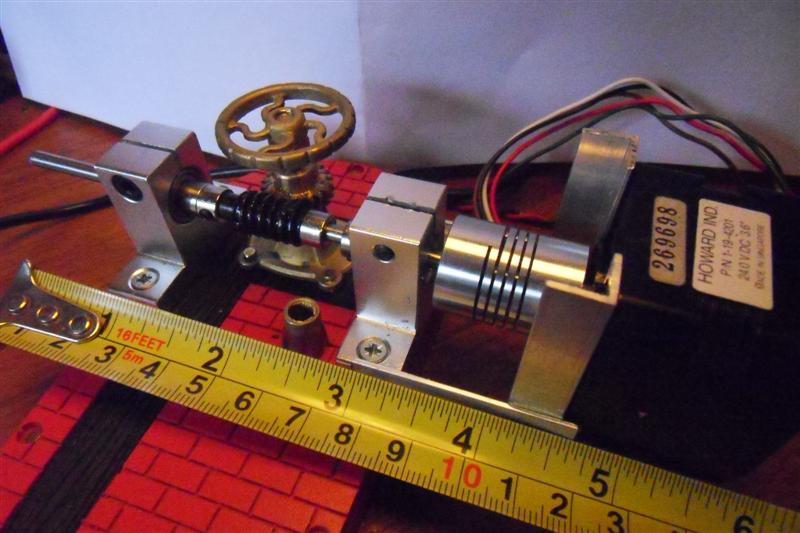
The turntable is internally fitted with a toothed belt between the bridge and the manual handwheel, with a 1:12 gear ratio.
The top part (shown on the picture next to the tape measure) of the housing of the handwheel axle has been cut away and a brass gear wheel is fitted to the axle beneath the handwheel.
The counterpart worm wheel (giving a ratio of 1:20) is fitted onto an axle, which is held in place by two grooved ball bearings plus holders (capable of taking axial and radial loads).
The steppermotor (100 steps/revolution) is connected to the axle via an aluminium flexible coupling.
The coupling also adjust for the difference in axle diameters (5 mm for the steppermotor and 4 mm for the worm wheel).
For one revolution of the bridge 12 * 20 * 100 = 24000 steps are needed.
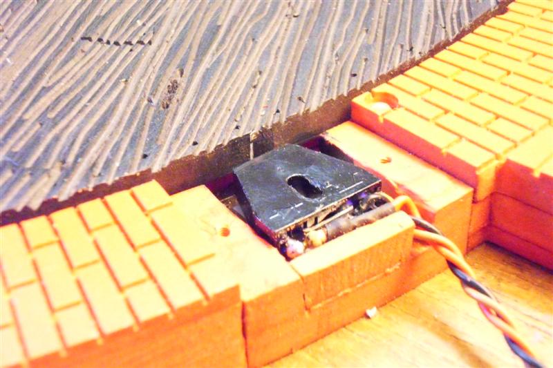
In the edge of the turntable a zero position detector is fitted (cover removed for the picture).
The detector consists of an infra-red led/photo-transistor combination with a focal point between 3 and 4 mm and a very narrow vertical stripe
of aluminium foil (showing as white on the picture) glued to the side of the black bridge cover.
New idea
Phytron beauty
Another satisfied user of GCA145 has sent me this solution:

This stepper motor has a gear box of 206:1 making 41200 steps for one full rotation!
Motor type : Phytron ZSS 52.200.2.5-HD 14/206
Through eBay he managed to buy this top product for a reasonable price.
There is no slack in the movement of this motor, so it is EXTREMELY right for the TT job.!
Full specs of the motor:
ftp://ftp.phytron.de/phytron-usa/stepper_motors/zss-hd-us.pdf
Recordplayer sacrifice
In Austria, Peter&Basti have been busy.
Unfortunately, they had to sell their record collection…

There is also a detailed explanation how this all is done.
doku_drehscheibenumbau.pdf


